
Click one of the buttons below to skip to the section you’d like to learn most about!
Wire and cable products often look simple when they arrive at a customer’s facility. A spool of spring wire, a reel of aircraft cable or a finished mechanical cable assembly may appear to be a straightforward product.
The manufacturing process behind it is anything but simple.
Material chemistry, surface preparation, diameter reduction, heat treatment, lubrication, forming, stranding, coating, termination and testing can all influence how the finished product performs. A small variation during one stage may affect strength, flexibility, surface quality, fatigue life, corrosion resistance or compatibility with downstream equipment.
Understanding how wire and cable are made helps engineers, technical buyers, quality departments and operations teams make better sourcing decisions. It also helps explain why two products with similar descriptions may behave very differently in the same application.
This guide provides an overview of the manufacturing journey, from raw material to finished wire, cable, wire rope or cable assembly.

Wire and Cable Manufacturing: Eight Common Questions
1. What goes into manufacturing high-performance wire and cable?
High-performance manufacturing begins with more than reducing metal to a specified diameter. The process may include reviewing the application requirements, selecting the alloy, preparing the incoming rod, drawing the material, controlling its mechanical properties, applying coatings or surface treatments, forming or stranding the product, testing it and packaging it correctly.
The exact sequence depends on the finished product. Fine Wire, Spring Wire, Shaped Wire, Welding Wire, Slicklines, Aircraft Cable and finished Cable Assemblies each require different combinations of equipment and process controls.
2. Why does wire consistency matter?
Consistency determines whether the material behaves predictably during manufacturing and in its final application. Variation in diameter, tensile strength, cast, helix, surface finish, coating, straightness or material condition can affect forming equipment, welding systems, spring coilers, cable pulleys, medical devices and other downstream operations.
A product can technically fall within a broad specification and still create production problems if its characteristics vary significantly from one package or production lot to another.
3. What happens inside a wire and cable manufacturing facility?
Depending on the product, manufacturing operations may include:
- Incoming material inspection
- Rod cleaning and surface preparation
- Wire drawing
- Annealing or stress relieving
- Wet or dry drawing
- Straightening and cutting
- Shaping or profile rolling
- Centerless grinding
- Stranding and closing
- Plastic extrusion or jacketing
- Cutting and termination
- Swaging or crimping
- Machining of fittings and components
- Destructive and non-destructive testing
- Spooling, labelling and packaging
Central Wire’s manufacturing capabilities include rod processing, rod breakdown, annealing, stress relieving, wet and dry drawing, Fine Wire drawing, cleaning, coating, straightening, centerless grinding, testing and packaging. Loos & Co. also has integrated cable operations including wire drawing, stranding and closing.

4. Where is wire and cable quality won or lost?
Quality can be affected at almost every stage. It may be lost before production begins if the wrong alloy, condition or specification is selected. It may also be affected by poor surface preparation, excessive drawing reductions, unsuitable heat treatment, worn tooling, inconsistent lubrication, uncontrolled stranding tension, improper coating thickness or a termination process that does not match the cable construction.
Quality is therefore not something that can be added during final inspection. It must be built into the process from the beginning.
5. Can a small process change improve durability?
Yes. Small changes can have a meaningful effect on downstream performance. A change in lubricant, coating, heat-treatment cycle, drawing sequence, die condition, cable construction or termination method may reduce friction, improve coiling, protect the surface, limit wire damage or improve fatigue resistance.
The best process change is not necessarily the largest one. It is the change that addresses the actual cause of a performance problem without creating a new issue elsewhere.
6. How do manufacturers control wire and cable tolerances?
Tolerance control begins with a clear and complete specification. Manufacturers then control the variables that influence the required measurement. Depending on the product, these may include tooling dimensions, drawing speed, die wear, temperature, tension, material condition, straightening equipment, cutting equipment, extrusion settings and inspection frequency.
Measurements may be taken throughout production instead of only after the product is complete. This allows operators and quality teams to identify process movement before a full production run is affected.
7. Where does wire and cable production most often go wrong?
Common problems include:
- Incomplete or unclear customer specifications
- Incorrect material selection
- Contaminated or poorly prepared surfaces
- Excessive variation between production lots
- Improper drawing or heat-treatment sequences
- Damaged or worn tooling
- Inconsistent lubrication
- Incorrect stranding tension or lay
- Coating adhesion or thickness problems
- Improperly selected fittings or termination methods
- Inadequate testing for the final application
- Packaging that damages or contaminates the product
Many of these issues are not isolated production failures. They are communication, specification or process-control failures that begin before manufacturing starts.
8. What separates commodity wire from engineered wire and cable?
Commodity material is generally purchased using a limited set of basic characteristics, such as alloy, diameter, construction and minimum strength. Engineered material is selected and manufactured around the way the product must function.
That may include tighter dimensional control, specific mechanical properties, a controlled surface finish, fatigue requirements, electrical resistance, corrosion resistance, package configuration, traceability, testing requirements or compatibility with automated equipment. The difference is not simply the name of the alloy. It is the level of control applied to the complete product and manufacturing process.
Understanding the Difference Between Wire, Strand, Cable and Cable Assemblies
Before examining the process, it is useful to distinguish between several related product types.
Wire
Wire is generally a single continuous metallic product manufactured to a controlled diameter or profile. It may be round, flat, square or custom shaped. Its properties can be adjusted for applications involving springs, welding, resistance heating, fasteners, filtration, medical components, oil and gas equipment, aerospace systems and general industrial manufacturing.
Strand
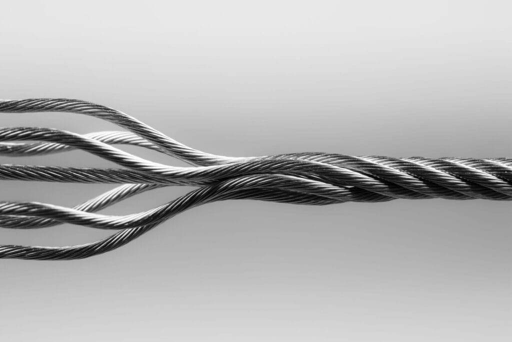
Strand is produced by combining multiple wires into a unified construction. A common example is a 1×7 strand, which contains one centre wire surrounded by six additional wires. Strand can provide a different combination of strength, stiffness and flexibility than a single wire of similar overall diameter.
Cable and Wire Rope
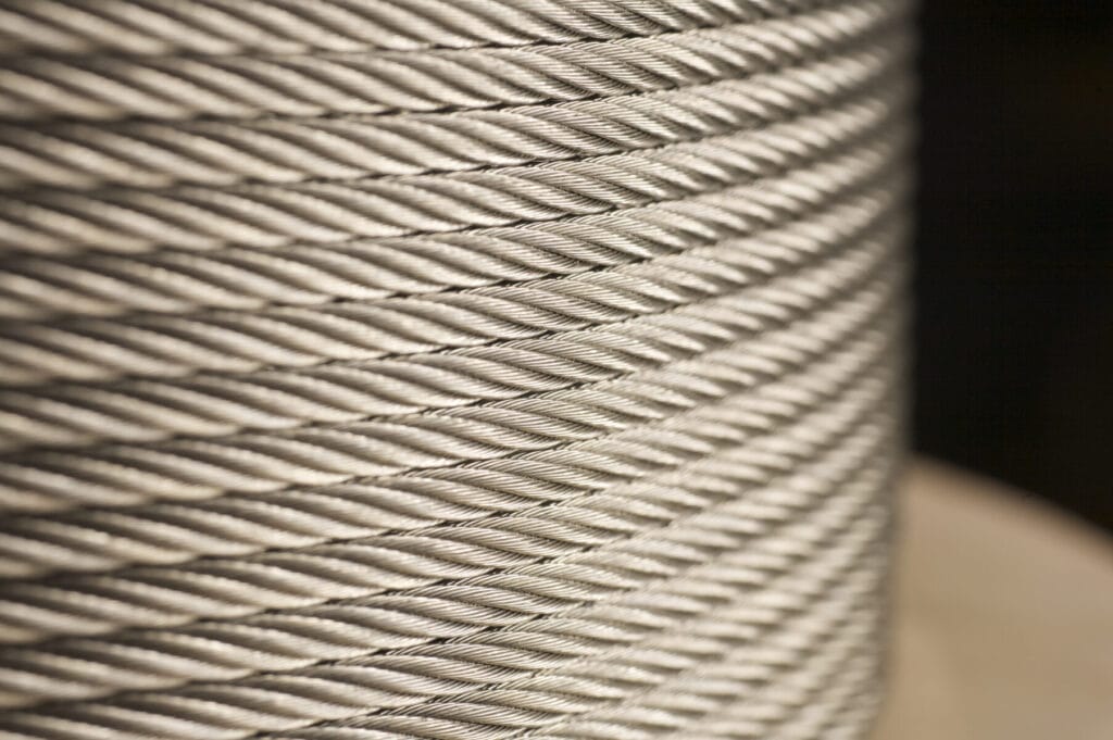
Cable and wire rope are manufactured by arranging wires or strands into specific constructions. Examples include 7×7 and 7×19 cable. The first number indicates the number of strands, while the second indicates the number of wires in each strand. The construction affects how the cable behaves.
A 7×7 construction is generally used when moderate flexibility is required, while a 7×19 construction is commonly selected for applications requiring greater flexibility and fatigue performance. Loos & Co. manufactures aircraft cable in constructions including 1×7, 1×19, 7×7, 7×19 and several larger wire-rope configurations. Available materials include Stainless Steel, Galvanized Steel, Carbon Steel and Specialty Alloys, depending on the product requirements.
Cable Assemblies
A cable assembly combines cable or wire rope with one or more fittings, terminals or manufactured components. The assembly may be cut to a specified length, fitted with terminations, swaged, crimped, formed, proof tested or otherwise prepared for installation.
In this case, performance depends on the entire system. The cable, construction, fitting, attachment method, finished length and operating environment must function together
Step 1: Translating the Application Into a Manufacturing Specification
Every successful manufacturing process begins with the application. A technical drawing or purchase description may identify the required alloy and diameter, but those details do not always explain how the product will be used.
Manufacturers may also need to understand:
- The operating temperature
- Exposure to moisture, chemicals or saltwater
- Static and dynamic loading
- Required flexibility
- Expected fatigue cycles
- Pulley or sheave dimensions
- Forming or coiling speeds
- Welding equipment and procedures
- Electrical requirements
- Surface-finish requirements
- Applicable industry standards
- Inspection and documentation requirements
- Final packaging and dispensing equipment
For example, selecting Spring Wire requires more than choosing a nominal diameter. The manufacturer may need to consider tensile range, alloy, temper, surface condition, coating, coil size and how the material will behave in high-speed coiling equipment.
Selecting Aircraft Cable may require decisions about construction, material, flexibility, breaking strength, coating, military or commercial specification and the type of fitting that will be added.
The more clearly the end-use conditions are defined, the more effectively the manufacturing process can be designed around them.
Step 2: Selecting and Verifying the Raw Material
Wire manufacturing typically begins with metallic rod or another larger starting form that will be reduced and processed. Material selection may involve Stainless Steel, Nickel Alloys, Copper Alloys, Galvanized or Carbon Steel and other specialty metals. The alloy is important, but so are its chemistry, initial diameter, surface condition, mill source and processing history.
A manufacturer may review material certifications and incoming inspection results before releasing the material into production. In regulated or mission-critical applications, traceability may need to connect the finished package or assembly to its original material heat or lot.
Material selection should reflect the actual operating environment. Stainless Steel may be selected for corrosion resistance, Nickel Alloys for demanding temperatures or chemical exposure, Galvanized Steel for strength and environmental protection, or Copper-based materials for electrical and thermal characteristics.
No amount of downstream processing can fully correct an alloy that was poorly matched to the application.
Step 3: Preparing the Rod Surface
Incoming rod may require cleaning, pickling, etching or coating before it can be drawn. This preparation removes scale, oxides, contamination and other material that could damage the drawing dies or become embedded in the finished wire surface.
Surface preparation also helps the drawing lubricant function correctly. Inadequate cleaning may contribute to scratches, die damage, inconsistent lubrication and premature wire breaks. Central Wire uses etching, pickling and coating among the methods used to prepare incoming wire rod for further processing.
This is one of the stages buyers rarely see, yet it can influence the appearance, cleanliness and consistency of the finished product.
Step 4: Drawing the Wire to Its Required Diameter
Wire drawing reduces the diameter of the material by pulling it through a series of dies. Rather than making one extreme reduction, the manufacturer normally uses multiple controlled reductions. Each pass decreases the diameter and changes the mechanical properties of the wire.
Drawing also causes work hardening. As the material is reduced, it generally becomes stronger and less ductile. The amount of reduction, die geometry, speed, lubrication and material temperature must therefore be managed carefully.
Dry Drawing
Dry drawing uses a dry lubricant and is commonly associated with larger wire diameters. It can produce a more matte surface and may be used where heat generation and die penetration are less significant concerns.
Wet Drawing
Wet drawing uses a liquid lubricant, which may be water- or petroleum-based. It is commonly used for smaller diameters where lubrication, cooling and die penetration become increasingly important. Wet drawing can also produce a smooth, bright surface.
Fine Wire Drawing
As wire diameter decreases, minor changes in tooling, tension, lubrication and surface condition become increasingly significant. Central Wire manufactures Fine Wire from 0.0035 inches at its Wire Division facilities, while its Pomfret Rope & Assemblies facility can manufacture sizes beginning at 0.001 inches. Available conditions range from soft annealed to spring temper.
At these sizes, controlling the process requires specialized dies, drawing fluids, inspection equipment and careful handling. A defect that appears minor on a larger wire can become a major percentage of the cross section of a very small wire.
Step 5: Controlling Strength, Ductility and Material Condition
Drawing changes the wire’s mechanical properties. Heat treatment may therefore be required between drawing stages or before the material is finished.
Annealing
Annealing uses controlled time and temperature to soften the material, restore ductility or adjust specific physical properties. This may allow the wire to undergo additional drawing or forming without cracking. It may also create the condition required for a customer’s manufacturing process.
Stress Relieving
Stress relieving reduces residual stresses introduced during drawing, forming or stranding. Depending on the alloy and product, it may help stabilize the material, improve straightness or support more consistent mechanical behaviour.
The correct cycle depends on the alloy, wire size, desired properties and subsequent operations. Heat treatment that is too aggressive may reduce strength beyond the desired range. Insufficient treatment may leave the product too hard or difficult to process.
Step 6: Cleaning, Coating and Surface Control
Lubricants are necessary during many wire-manufacturing operations, but the residue may need to be removed before heat treatment, coating, welding, medical use or another downstream operation.
Cleaning can involve aqueous washes, alkaline solutions or other controlled methods.
The surface may then receive a coating for one of several reasons:
- To improve lubrication during forming
- To reduce friction in downstream equipment
- To provide short-term surface protection
- To improve corrosion resistance
- To support high-speed coiling
- To create a required appearance
- To prepare the material for another manufacturing operation
For Spring Wire, a coating that reduces friction may improve feed consistency and reduce stress on coiling equipment. Central Wire offers Spring Wire in several Stainless Steel and Nickel Alloy grades, with coating options intended to support manufacturability and end-use performance.
The important point is that a coating should be selected as part of the manufacturing system. A coating that performs well in one operation may interfere with welding, cleaning, bonding or another process.

Step 7: Creating Round, Shaped or Precision-Finished Products
Not every wire product remains round. Shaped Wire can be manufactured in flat, square, rectangular, wedge-shaped or more complex custom profiles. Edge conditions may include square, rounded, natural rolled or fully rounded configurations.
These details affect fit, contact area, flow, filtration, movement and stress distribution in the final application.
Central Wire produces profiled wire with multiple edge configurations and offers Stainless Steel, Nickel and Specialty Alloy options for applications that include filtration, springs, furnace belts, pins and specialist engineering. Other products may require straightening, cutting or centerless grinding.
For bar and cold-heading applications, centerless grinding can create a controlled outside diameter and surface finish. Straightening and cutting convert coiled product into lengths that can be machined, headed, ground or otherwise formed.
This demonstrates why “wire manufacturing” does not describe one universal process. The production route is determined by the geometry, material condition and final application.
Step 8: Manufacturing Strand, Cable and Wire Rope
Once individual wires meet the required properties, they can be combined into strand, cable or wire rope. Loos & Co. has integrated manufacturing capability through wire drawing, stranding and closing wire rope.
During stranding, individual wires are arranged helically around a centre wire or core. During closing, strands may be combined to create a larger cable or wire-rope construction.
Important variables include:
- Wire diameter
- Number of wires
- Strand construction
- Direction of lay
- Length of lay
- Closing tension
- Core selection
- Preforming
- Lubrication
- Finished diameter
- Breaking strength
These variables influence flexibility, rotational behaviour, fatigue resistance, handling and load capacity. A construction with more and smaller wires will generally behave differently than one with fewer and larger wires, even when the finished diameters are similar.
This is why cable construction should not be treated as a secondary specification. It is one of the primary factors determining how the cable moves and performs.
Step 9: Applying a Protective Cable Coating
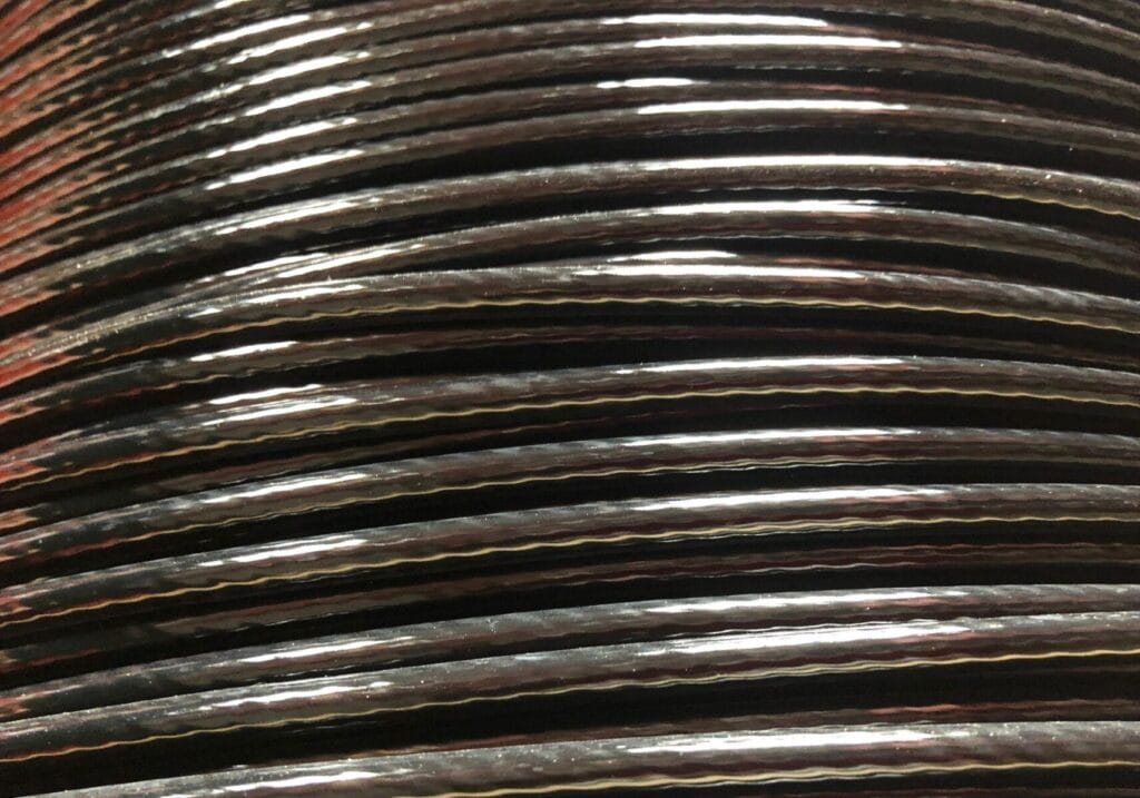
Cable may be supplied bare or coated with materials such as Nylon, Vinyl, Polyethylene or Polypropylene.
The coating is commonly applied by extrusion. Cable and coating material pass through controlled tooling to create the required jacket thickness and outside diameter.
The coating may provide:
- Abrasion protection
- Environmental protection
- Improved handling
- Reduced contact damage
- Colour identification
- A smoother exterior
- Separation between the metallic cable and nearby components
Loos & Co. applies plastic jackets to standard Aircraft Cable and Wire Rope, with Nylon and Vinyl among its available coating options. The coating is intended to improve durability, functionality and resistance to demanding environmental conditions. The coating does not replace proper cable selection. The base cable construction, alloy and strength still need to match the application.
Coating thickness and concentricity also matter. An inconsistent outside diameter can interfere with pulleys, guides, housings and automated equipment.
Step 10: Turning Cable Into a Finished Assembly
A cable assembly is produced when cable is cut to length and combined with fittings, terminals or other components.
Depending on the design, operations may include:
- Electrical or mechanical cutting
- End preparation
- Swaging
- Crimping
- Forming loops
- Installing sleeves or terminals
- Adding threaded fittings
- Machining custom hardware
- Setting the finished assembly length
- Prestretching
- Proof loading
- Inspection and identification
A reliable assembly requires compatibility between the cable and fitting. The termination must grip the cable without causing unacceptable wire damage. The fitting material must suit the environment. The finished length must account for the cable construction, fitting geometry and any load-related requirements.
Loos & Co. manufactures custom Cable Assemblies to customer specifications using bare or coated cable, fittings and hardware. Its assembly capabilities cover commercial, aerospace, military and medical applications, including both high-speed electrical cutting and mechanically cut cable produced to controlled lengths.
For buyers, this is an important distinction. Purchasing cable and fittings separately does not automatically create a qualified assembly. The completed connection must be manufactured and evaluated as a system.
Step 11: Testing Throughout the Process
Final inspection is important, but it cannot be the only point of control. Effective quality systems use inspection and testing at multiple stages. This may include incoming material review, in-process dimensional checks, mechanical testing, surface inspection and finished-product verification.
Depending on the product and specification, testing may evaluate:
- Diameter
- Tensile strength
- Yield strength
- Elongation
- Hardness
- Torsion
- Wrap or bend performance
- Coiling behaviour
- Electrical resistance
- Conductivity
- Surface finish
- Coating weight
- Corrosion resistance
- Breaking strength
- Proof load
- Assembly length
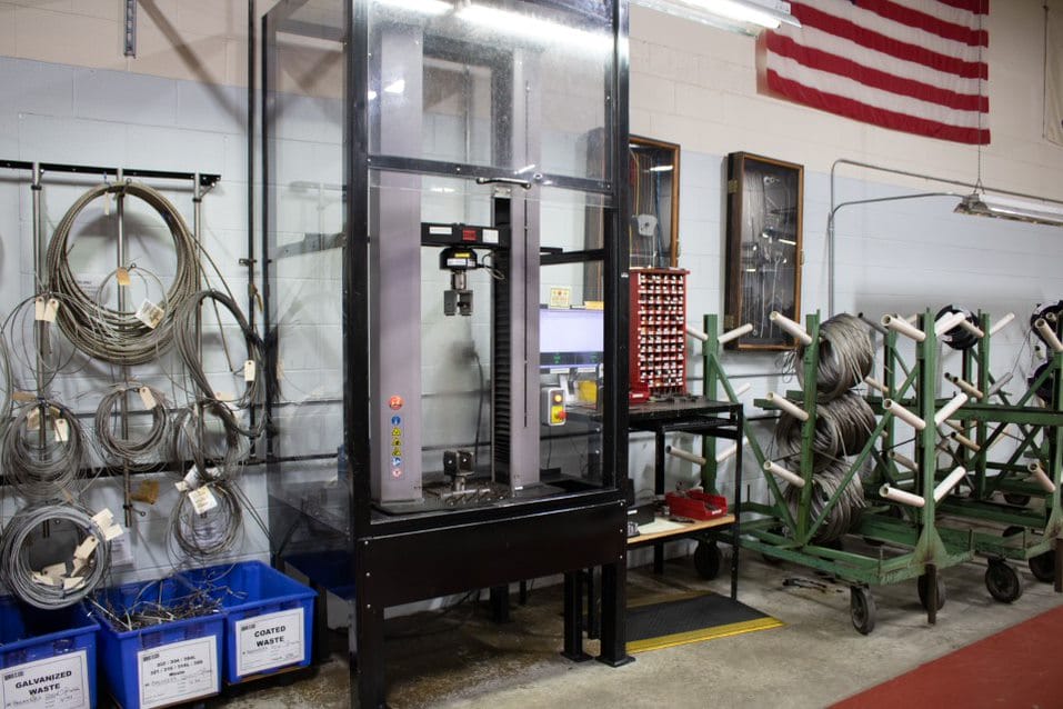
Central Wire lists testing methods covering tensile strength, torsion, cold bending, coiling, wrapping, metallography, hardness, intergranular corrosion, coating weight and electrical resistance. Product certification testing is performed in accordance with applicable ASTM and ISO/EN standards.
Destructive Testing
Destructive testing determines how a representative sample behaves when it is pulled, bent, twisted, wrapped or otherwise tested to a defined limit or point of failure.
It provides information about the product’s mechanical properties and verifies that the manufacturing process is producing the intended result.
Non-Destructive Testing
Non-destructive testing evaluates material or components without making them unusable.
Loos & Co.’s listed non-destructive testing capabilities include Ultrasonic Testing, Radiographic Testing, Magnetic Particle Testing, Fluorescent Penetrant Inspection, Eddy-Current Testing and Visual Testing. These methods can identify defects that may not be visible during a standard surface inspection.
The required testing level should be based on the application risk, specification and customer requirements rather than applied uniformly to every product.
Step 12: Packaging, Identification and Traceability
Manufacturing is not complete when the product leaves the final machine. Wire can be damaged by poor winding, unsuitable spool dimensions, contamination, excessive tension or improper handling. Cable assemblies can be bent, tangled or mixed if packaging is not designed around their size and geometry.
Packaging decisions may include:
- Spool, reel, coil, bobbin, drum or cut-length packaging
- Package weight
- Winding pattern
- Payoff direction
- Core size
- Protective wrapping
- Moisture protection
- Individual assembly packaging
- Lot separation
- Labelling and identification
- Customer-specific kitting
A package that works well for transportation may not work well with the customer’s dispensing or production equipment. Package design should therefore be treated as part of the manufacturing specification.
Traceability is equally important. Labels and certifications may need to identify the alloy, heat, production lot, size, specification, quantity and inspection status.
For aerospace, medical, military and other controlled applications, documentation can be nearly as important as the physical product. Loos & Co.’s manufacturing operations maintain certifications that include ISO 9001:2015, AS9100 for aerospace and ISO 13485:2016 for medical products.
Why Consistency Matters More Than a Single Passing Test
A passing test confirms that a sample met a defined requirement at a particular moment.
Consistency answers a broader question: will the material continue to behave predictably across the full package, production lot and future orders?
- Consider a Spring Wire that meets its tensile requirement but varies in cast or surface lubrication. The material may still create inconsistent feed behaviour in a coiling machine.
- A Welding Wire may meet its chemistry requirement but create feed or arc-stability problems if diameter, surface condition or packaging varies.
- A cable may meet minimum breaking strength but perform poorly in a repeated-bending application if its construction is not appropriate for the pulley system.
- A cable assembly may pass a dimensional inspection but still create installation problems if the finished length changes after loading.
- Technical buyers should therefore look beyond the certificate value and consider how the supplier controls the complete production process.
Where Manufacturing Problems Commonly Begin
Manufacturing failures are often traced to one of four areas.
- The Specification Was Incomplete
Terms such as “Stainless Steel Wire” or “Aircraft Cable” are not complete specifications. The requirement may also need to identify alloy, diameter, tolerance, temper, tensile range, construction, coating, finish, length, fittings, testing, packaging and applicable standards.
- The Product Was Selected by Price Before Performance
The lowest initial material price may not produce the lowest operating cost. Material that causes downtime, tool wear, rejected components, installation delays or early field failures can create costs far beyond the original purchase price.
- The Supplier Controlled the Final Result but Not the Process
Inspecting the final diameter is necessary, but it does not reveal every process issue. A stable process controls the variables that create the diameter, strength, finish and other required properties.
- The Manufacturing Process Was Not Connected to the Application
Material should not be manufactured in isolation from its end use. A supplier that understands forming, welding, fatigue, corrosion, loading and installation requirements is better positioned to identify risks before production begins.
Commodity Material Versus Engineered Performance
Commodity products have an important place in manufacturing. Many applications can be served effectively by standard alloys, constructions, sizes and packaging. Problems occur when a standard product is expected to perform like an application-specific one.
An engineered wire or cable solution may require:
- A specific alloy or material condition
- Tighter diameter or length tolerances
- A controlled tensile range
- A defined surface finish
- A specialized coating
- A custom profile
- A fatigue-resistant cable construction
- Application-specific testing
- Custom packaging
- Full material traceability
- A finished assembly rather than separate components
The goal is not to specify the most complex product possible. It is to control the characteristics that materially affect performance. Over-specification can add unnecessary cost. Under-specification can create inconsistency, downtime and risk. The most effective specification is the one that clearly connects manufacturing requirements to the demands of the application.
Questions Technical Buyers Should Ask a Wire and Cable Manufacturer
Before approving a supplier or placing a new product into production, buyers and engineers should consider asking:
- What information is required to confirm the correct alloy, construction and material condition?
- Which manufacturing operations are performed internally?
- How are incoming materials verified?
- Which characteristics are inspected during production?
- How are drawing dies, stranding equipment and other critical tooling monitored?
- What testing is available for the product and application?
- Can the supplier meet the required ASTM, ISO, AMS, military or customer-specific specification?
- How is traceability maintained from raw material to finished package?
- Can packaging be matched to the customer’s production equipment?
- What technical support is available if the material behaves differently during production?
- Can the supplier support prototypes as well as production quantities?
- Can wire, cable, fittings and finished assemblies be sourced through an integrated manufacturing process?
These questions provide more useful information than simply asking whether a supplier can produce a particular diameter or construction.
How Wire and Rope & Assembly Manufacturing Work Together
Wire and Rope & Assemblies manufacturing are closely connected.
The characteristics created during wire drawing influence how that wire strands, closes, bends, coats and terminates. Cable construction determines how the finished product moves through a pulley or carries a load. Fittings and swaging methods determine how effectively the cable’s strength is transferred into an assembly.
Looking at these processes as one connected system helps manufacturers and customers address performance at the correct stage. Across the Central Wire Group of Companies, these capabilities extend from Specialty Wire manufacturing to Strand, Aircraft Cable, Wire Rope, Coated Cable, Cable Assemblies, fittings and precision-manufactured components.
This integrated perspective is relevant across applications that include:
- Aerospace controls and emergency systems
- Medical Wire and Cable Assemblies
- Automotive controls
- Springs and formed components
- Welding operations
- Oil and gas equipment
- Marine systems
- Fitness equipment
- Architectural cable
- Filtration products
- Fasteners and machined components
- Industrial control systems
The finished products may look different, but the manufacturing principles remain connected: select the correct material, control the process, verify the result and understand the application.
Final Takeaway
Wire and cable manufacturing is not one operation. It is a sequence of controlled decisions. Raw material selection influences drawing. Drawing influences strength and ductility. Heat treatment affects formability. Surface preparation affects tooling and downstream production. Stranding affects flexibility and fatigue. Coating affects protection and fit. Termination affects assembly strength. Testing confirms whether the process achieved the required result.
The most reliable products are not created by inspecting quality into the material at the end. They are created by controlling quality throughout the entire manufacturing process. For engineers, buyers and quality teams, understanding how the product is made provides a stronger basis for evaluating specifications, comparing suppliers and preventing avoidable production problems.
When the manufacturing process is aligned with the application, wire, cable and cable assemblies become more than basic components. They become predictable, engineered parts of the systems in which they operate.